First, the reason this happens:
When rendering a triangle, your GPU evaluates 2x2 blocks of pixels at a time. That means when you sample a texture in a fragment shader, the GPU has 4 sets of texture coordinates to work with. It looks at the differences between these 4 texture coordinates (screenspace partial derivatives) to estimate how much the texture is being stretched in this neighbourhood - either due to the camera being close/far, looking at the surface at an angle, or due to intrinsic stretching in the model's UV unwrap. With this information, it can automatically select the right mipmap to read from, or apply the right amount of anisotropic filtering, so that the texture comes out looking the best it can: not sparkly and aliased from undersampling, and not unnecessarily blurry.
The trouble is that when we calculate texture coordinates for an equirectangular projection / spherical coordinates, one of these 2x2 screenspace pixel blocks can straddle the wrap-around point from just-shy-of-one to just-past-zero in the longitude direction. As far as the GPU is concerned, that means the entire texture has been compressed down, so that 100% of its width fits across a 1-pixel stride, and it auto-selects the smallest mip to sample from. You end up with the average colour of the whole texture, instead of the appropriately-filtered colour for the part of the sphere you were actually trying to render.
Here is a graph that fixes this seam in Unity URP:
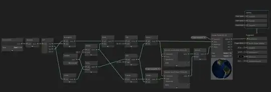
The idea here is that we calculate two texture coordinates: one with the wrap-around point in the normal place, and one where we've moved the wrap-around point to the other side of the sphere. We calculate what level of detail should be used for each attempt, and when they disagree (when one says the block straddles the wrap-around and the other doesn't), we pick the smallest one. Then finally we sample the texture with that "least-of-two" LoD estimates.
One downside with this approach is that we lose anisotropic filtering, so you may find the glancing edges of the sphere appear more blurry than you'd like.
In shader code, we can use the tex2Dgrad function or equivalents to do a similar trick while supporting anisotropy, but as you've found, this function isn't currently exposed to the Unity shader graph - we'd have to use a Custom Function node to inject raw shader code to access it.
A simpler solution though, and one that may scale better for your needs, is to store your spherical textures not as 2D equirectangular rectangles, but as cubemaps. This gives a more even texel density over the surface of the sphere, so you can get away with smaller textures for the same worst-case detail, or better detail with the same texture memory. Filtering for these is already supported out-of-the-box, so your shader stays simpler too.


