First, a general statement: the antenna analyzer has one set parameter, the frequency, and one measured parameter, the impedance (which is a complex number and therefore requires two real numbers to display).
Everything else can be derived, one way or the other.
Why for Z & Zpar are there 2 numbers, one with a j in front. What do those mean?
$Z$ stands for impedance, which is a complex number and so has to be written as made up of two real numbers. (Mathematicians write complex numbers with an $i$ instead of a $j$, but it means the same thing.) I won't explain complex numbers here — there's many different introductions and you should find one that makes sense to you.
Impedance is a quantity analogous to resistance which is useful in analyzing radio-frequency systems in the same way as resistance is useful in analyzing DC systems, and much of the math is the same; you just need to use complex arithmetic instead of real arithmetic.
Any time you see someone refer to the impedance of an RF device as, say, $50\,\Omega$, it's “really” $(50 + j0)\,\Omega$ — that is, the complex number has a zero “imaginary part” and since it is zero we can leave it out (after all, anything multiplied by zero is zero and adding zero doesn't change a number, so $50 + j0 = 50 + 0 = 50$.)
Impedance corresponds to resistance whenever the imaginary part is zero; when it's nonzero, that means the thing that has that impedance resembles an inductor or a capacitor (it can't be both) at that frequency. The imaginary part is called reactance. Reactance is like resistance except that instead of dissipating energy, it releases it later in some way.
- The impedance of an ideal resistor is always $(x + j0)\,\Omega$ for some $x$.
- The impedance of an ideal capacitor is always $(0 - jx)\,\Omega$ for some $x$.
- The impedance of an ideal inductor is always $(0 + jx)\,\Omega$ for some $x$.
When you get into more complex (and realistic) circuits, including an antenna at the end of a length of transmission line, both will be nonzero. (Or, a simple example: as you may know, if you put two resistors in series you add their resistances. The same implies to impedances: if you have an inductor with impedance $Z_L$ and a resistor with impedance $Z_R$ in series, the impedance will be $Z_L + Z_R = jx\,\Omega + y\,\Omega = (x + jy)\,\Omega$ for the particular $x$ and $y$.)
What is the difference between Z & |Z| & Zpar?
$|Z|$ is the magnitude of the impedance. Imagine you take the two parts of the complex number and use them to mark a point on graph paper; the magnitude is the distance from the origin (i.e. the square root of the sum of the squares).
I don't offhand remember what $|Z|$ is good for when analyzing antennas.
$Z_{\text{par}}$ should be the same as $Z$, I would think, because there's only one impedance value regardless of the model (see below for explaining "par").
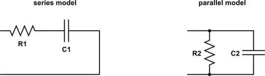
What is the difference between C & Cpar?
$C$ is capacitance, but the impedance (or reactance) of a capacitor is not only dependent on its capacitance, but also the frequency. But the analyzer knows the frequency being applied, so it can compute "If we assume the circuit under test is actually a resistor in series with a capacitor, what is the capacitance that would produce the observed impedance at this frequency?"
$C_\text{par}$ is the same, except that it is for the model of a resistor in parallel with a capacitor instead of in series.
If the analyzer displays $L$ values, they are the same except that the circuit is more like an inductor than a capacitor and it is displaying those values.