8

Z80 was a popular 8-bit processor with a 4-bit ALU.
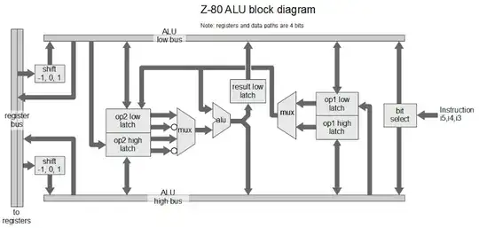
Z80 ALU

Implementing a zero flag for a register should be straight forward, it would be a logical NOR of all the bits on the register.
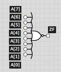
Gigantic NOR

Something like that would work for a small number of inputs. As for a 64-bit processor you cannot make one gigantic NOR gate with 64 inputs. The fan-in would be too high. 8 transistors would be in series. The circuit capacitance would be high thus slowing down everything else.

I can see some other options.

  • The zero flag could be generated directly from the 8-bit result using 2 level logic.
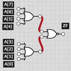
two level logic two level logic

  • The zero flag could be generated directly from the 8-bit result using 3 level logic.

three level logic

  • The zero flag could be generated from each nibble and then put together, like if there was a "half"-zero flag. The result for the lower would be saved using a flip-flop while waiting for the high nibble result to be calculated.

Nibble

Ken Shirriff wrote a nice article about reverse engineering the Z80 ALU. However when it comes to the zero flag he states:

Not shown in the block diagram are the simple circuits to compute parity, test for zero, and check if a 4-bit value is less than 10. These values are used to set the condition flags.

So, although they are simple circuits I would like to know exactly how they were implemented and if they used any of the implementations proposed above or something else completely different.

  • 2
    Your assertion that the "fan in would be too high" has hidden assumptions that may not be valid. – caskey Apr 24 '15 at 06:57
  • @caskey please explain – GabrielOshiro Apr 24 '15 at 12:33
  • 1
    Please ask instead at http://electronics.stackexchange.com/ – Jason Geffner Apr 24 '15 at 14:14
  • 2
    @JasonGeffner The question is about reverse engineering. I want to know exactly how something was implemented. I have no doubts on how the electronics behind it work. – GabrielOshiro Apr 24 '15 at 16:43
  • 1
    @GabrielOshiro nice images but you forget the simplest one: wired or + single negator. The zero flag can be located anywhere (ALU,Register file,any of the data BUS,...) and also would need some gating because not all operations change ZF. The truth can be found only by examinaning the DIE (which is time consuming) or ask someone that created the Z80 circuitry/die masks inside Zilog Company ...or the clones copies like U880A ... – Spektre Apr 28 '15 at 11:33
  • "The question is about reverse engineering." -- No, you stated in your comment below that you don't want to reverse engineer it, even though @Spektre told you how to do it in the answer posted below. This is a reverse engineering forum, and given that you've stated below that you don't want to reverse engineer the target, your question belongs on electronics.stackexchange.com. – Jason Geffner Apr 28 '15 at 14:13
  • @JasonGeffner Just because I don't want to reverse engineer the z80 myself, it does not mean that I am not allowed to come here and post a question for those that have done it already. Any further discussion about where the question should be posted should be addressed [on meta exchange][http://meta.stackexchange.com/questions/254276/reverse-engineering-or-electronics]. Feel free to vote to close the question if you find applicable. – GabrielOshiro Apr 28 '15 at 16:30
  • @Spektre I have contacted Zilog and Sharp (concerning the LR35902 processor) and there is no way they will give me that information. The way to go is to find someone that works with the reverse engineering. That is why I am asking the question here. – GabrielOshiro Apr 28 '15 at 16:33
  • @Spektre Is a wired OR + NOT a possibility? I did not know that... thanks for the info. – GabrielOshiro Apr 28 '15 at 16:37
  • @GabrielOshiro, thanks for posting your question on Meta! And despite how my comments above may sound, I really do want you to be able to find the answer to your question; I'm just of the opinion that you might have better luck on Electronics. Either way, good luck! – Jason Geffner Apr 28 '15 at 16:41
  • 1

1 Answers1

13

Well if you want to know how it was done exactly

Then download the Z80 die shot of model you want to investigate, crop the ALU part and identify all the gates you can until you dig to Zero flag your self (sorry for indirect answer).

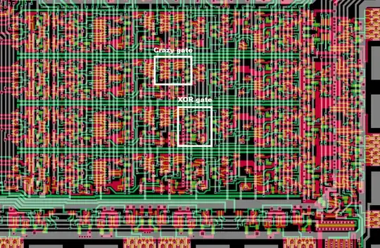
Here my Z80 ALU post processed die shot

Z80 ALU

  • white - metal
  • green - poly-Si
  • red - dopped-Si (diffusion)
  • Gray - conductive joints between layers

Try to identify all gates and buses you can (and mark them to the image)

Z80 ALU labeled

When found familiar structure like Wire OR, (N)OR cascade, ... then you will know for sure. Just try to find the basic components like:

Components

form the circuit schematics and make some sense of it.

Spektre
  • 1,384
  • 7
  • 13