4

I wanted to look at the matrix representation of CNOT gate as defined in Qiskit.

from qiskit import Aer
from qiskit.circuit import Gate
from math import pi
qc = QuantumCircuit(2)
c = 0
t = 1
qc.cx(c,t)
qc.draw()
____________________

Out[4]:
q_0: ──■── ┌─┴─┐ q_1: ┤ X ├ └───┘ ____________________

import qiskit.quantum_info as qi

op = qi.Operator(qc) print(op) ____________________

Operator([[1.+0.j, 0.+0.j, 0.+0.j, 0.+0.j], [0.+0.j, 0.+0.j, 0.+0.j, 1.+0.j], [0.+0.j, 0.+0.j, 1.+0.j, 0.+0.j], [0.+0.j, 1.+0.j, 0.+0.j, 0.+0.j]], input_dims=(2, 2), output_dims=(2, 2))

I am a bit confused, as I expected to see \begin{matrix} 1 & 0 & 0 & 0\\ 0 & 1 & 0 & 0\\ 0 & 0 & 0 & 1\\ 0 & 0 & 1 & 0 \end{matrix}

What Qiskit output as the matrix representation of CNOT looks to me like CNOT with the first qubit as target and second qubit as control.
glS
  • 24,708
  • 5
  • 34
  • 108
Blackwidow
  • 599
  • 2
  • 8

2 Answers2

5

It is because the state ordering convention. In qiskit, the states are ordered as $|00\rangle$, $|01\rangle$, $|10\rangle$, $|11\rangle$.

If you flip the values of c and t in your code, you will get the matrix you were expecting.

Guangliang
  • 205
  • 1
  • 7
0

Qiskit uses Little Endian convention, in which the n-th qubit is written on the left side of the tensor product and the zero qubit is written on the right side: $$ q_{(n-1)}⊗…⊗q_1⊗q_0 $$ Thus, having three qubits such that the first qubit is in state 1, and the second and third qubits are in state 0, we will write this in Qiskit as $|001⟩$.

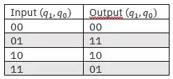
As for the $CNOT$ matrix, assuming we follow the Little endian convention, $q_0$ is the control qubit and $q_1$ is the target qubit, the truth table will look like this:

enter image description here

There is a nice rule how to construct controlled gates in Qiskit. Assuming that we have a one-qubit gate $U$ represented by matrix: $$U=\left(\begin{array}{cc} u_{00}&u_{01}\\ u_{10}&u_{11} \end{array}\right)$$ then its controlled version in Qiskit will have following matrix: $$C_u=\left(\begin{array}{cccc} 1&0&0&0\\ 0&u_{00}&0&u_{01}\\ 0&0&1&0\\ 0&u_{10}&0&u_{11} \end{array}\right)$$ So if $NOT$ gate has following matrix: $$U=\left(\begin{array}{cc} 0&1\\ 1&0 \end{array}\right)$$ Then $CNOT$ will be: $$C_u=\left(\begin{array}{cccc} 1&0&0&0\\ 0&0&0&1\\ 0&0&1&0\\ 0&1&0&0 \end{array}\right)$$