Already some good answers here but here's how I try to visualize it. It consists of steps that are redundant but nonetheless useful for visualization.
This might be kinda long but I'm writing it in a way will be helpful to me if I need to revisit it, and therefore hopefully helpful to others.
Let's begin with
$$
A = \begin{bmatrix}
a & d & g \\
b & e & h \\
c & f & i
\end{bmatrix}
$$
and picture the paralellepiped formed by the 3 column vectors.
$$
\left[
\left({\begin{matrix} a \\ b \\ c \end{matrix}}\right)
\left({\begin{matrix} d \\ e \\ f \end{matrix}}\right)
\left({\begin{matrix} g \\ h \\ i \end{matrix}}\right)
\right]
$$
Assume A is invertible (nonzero determinant).
Without loss of generality, let's picture the parallelogram formed by
$ B =
\left[
\left({\begin{matrix} d \\ e \\ f \end{matrix}}\right)
\left({\begin{matrix} g \\ h \\ i \end{matrix}}\right)
\right]
$
to be the base (let's call it the floor) part of our parallelepiped, and consider $\vec{h} =
\left({\begin{matrix} a \\ b \\ c \end{matrix}}\right)
$ to be the "height" (let's call it the beam) part. Don't confuse $\vec{h}$ with the element in $A$ also called $h$.
The two column vectors in B exist in a 2d plane.
By Cavalieri's principle, the only thing that matters about $\vec{h}$ is how far it goes (technically in a signed sense) in the direction orthogonal to the plane that $B$ lies in -- that is, in the direction that is orthogonal to both columns of $B$, i.e. orthogonal to $B$'s column space. What's the actual height, not the length of the beam. This is why you can have a stack of paper and "smear" it around, creating various parallelepiped shapes with a fixed sheet-of-paper-shaped floor without changing the volume of the stack.
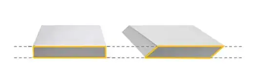 Given the area of the floor, the cubic footage of your bedroom isn't strictly determined by the length of the beams holding up the ceiling. What really matters is the height of the beams -- i.e., how far is the ceiling from the floor. If your beams are dramatically tilted, you'll lose cubic footage. Tilting the beams doesn't change their length but it changes their height.
Another way to think about it is if you're rowing a boat (or shoveling snow), it's most effective to have the flatness of the oar (the plane) perpendicular to the direction of the stroke because you're displacing the most water (or snow) that way. In this case the flat base of the oar is like the base of the parallelepiped and the component of the stroke orthogonal to this base is the height.
Unfortunately, we can't usually look at $A$ and "read off" the area of the $B$ parallelogram (the floor) and the "orthogonal height" of $\vec{h}$. This is because $B$'s plane doesn't always conveniently lie in an axis-aligned plane.
There are a number of ways you could go about obtaining a unit vector in the direction orthogonal to $B$'s column space. This would be the normalized cross product of the columns of $B$ but I won't get into that.
Let's just say we have it and that it's called $\vec{u}$. Note that $\vec{u}$ is (the only direction, aside from scaling) in the left null space of $B$.
We can formalize Cavalieri's principle as follows:
For any $\vec{h}$,
$$\tag{*} det \left[
\vec{h}
\left({\begin{matrix} d \\ e \\ f \end{matrix}}\right)
\left({\begin{matrix} g \\ h \\ i \end{matrix}}\right)
\right] =
det \left[
proj_{\vec{u}}\left(\vec{h}\right)
\left({\begin{matrix} d \\ e \\ f \end{matrix}}\right)
\left({\begin{matrix} g \\ h \\ i \end{matrix}}\right)
\right]
$$
We're going to use this multiple times in this visualization. The visualization consists of morphing our parallelepiped without changing its volume, then slicing it up, then morphing those slices without changing their volumes, then adding up the volumes of those slices to get the total volume.
Step 1: straighten out the parallelepiped
Replace $A$ with
$$
S =
\left[
proj_{\vec{u}}\left(\vec{h}\right)
\left({\begin{matrix} d \\ e \\ f \end{matrix}}\right)
\left({\begin{matrix} g \\ h \\ i \end{matrix}}\right)
\right]
$$
By "replace" I mean that we're informally transforming $A$ in our minds into $S$, and by (*), we're not changing the volume, so we can use $S$ to find the determinant of $A$. Now that our new beam is orthogonal to the floor, the height of this beam is just the length of the beam.
Step 2: slice up the straightened parallelepiped
We will use linearity of the projection:
$$
proj_{\vec{u}}\left(\left({\begin{matrix} a \\ b \\ c \end{matrix}}\right)\right) =
proj_{\vec{u}}\left(\left({\begin{matrix} a \\ 0 \\ 0 \end{matrix}}\right)\right) +
proj_{\vec{u}}\left(\left({\begin{matrix} 0 \\ b \\ 0 \end{matrix}}\right)\right) +
proj_{\vec{u}}\left(\left({\begin{matrix} 0 \\ 0 \\ c \end{matrix}}\right)\right).
$$
The above is deserving of its own visual/intuitive explanation but it'd be too much to go into it here.
But what we'll do is use this fact to slice up $S$ into three parallelepipeds with the same floor shape and all with beam vectors orthogonal to the floor (three stories in the same building), albeit with different heights. The heights are determined by the projection of the $x$, $y$, and $z$ components of $\vec{h}$ onto $\vec{u}$. We'll name the respective matrices $S_x$, $S_y$, and $S_z$.
For example,
$$
S_x =
\left[
proj_{\vec{u}}\left(\left({\begin{matrix} a \\ 0 \\ 0 \end{matrix}}\right)\right)
\left({\begin{matrix} d \\ e \\ f \end{matrix}}\right)
\left({\begin{matrix} g \\ h \\ i \end{matrix}}\right)
\right]
$$
$$
S_y =
\left[
proj_{\vec{u}}\left(\left({\begin{matrix} 0 \\ b \\ 0 \end{matrix}}\right)\right)
\left({\begin{matrix} d \\ e \\ f \end{matrix}}\right)
\left({\begin{matrix} g \\ h \\ i \end{matrix}}\right)
\right]
$$
$S_z$ will be similarly defined with its respective piece of the projection.
Then we have
$$det\;S = det\;S_x + det\;S_y + det\;S_z$$
The big caveat here is that some of the slices can have negative volume and some positive. So stacking negative and positive slices of paper would be like adding two stacks of paper on top of each other, and then removing some off the top. The last operation was adding a negative stack of paper.
This corresponds to the fact that if you move $\vec{h}$ toward $x$, it might increase the volume by increasing the height of the paralellepiped because positive $x's$ projection (or the projection of basis vector $\hat{i}$ if you like) onto $\vec{u}$ is positive, whereas moving $\vec{h}$ toward $z$, for instance, might decrease volume because $z's$ projection onto $\vec{u}$ is negative. Remember, increasing or decreasing the projection onto $\vec{u}$ means increasing our decreasing the effective height in base times height.
Another way to picture this is by imagining traveling from one vector to the next as follows
$$
\left({\begin{matrix} 0 \\ 0 \\ 0 \end{matrix}}\right) \to
\left({\begin{matrix} a \\ 0 \\ 0 \end{matrix}}\right) \to
\left({\begin{matrix} a \\ b \\ 0 \end{matrix}}\right) \to
\left({\begin{matrix} a \\ b \\ c \end{matrix}}\right)
$$
When we take each one of these consecutive steps, our projection onto $\vec{u}$ increases or decreases, like
$$
proj_{\vec{u}}\left(\left({\begin{matrix} 0 \\ 0 \\ 0 \end{matrix}}\right)\right) \to
proj_{\vec{u}}\left(\left({\begin{matrix} a \\ 0 \\ 0 \end{matrix}}\right)\right) \to
proj_{\vec{u}}\left(\left({\begin{matrix} a \\ b \\ 0 \end{matrix}}\right)\right) \to
proj_{\vec{u}}\left(\left({\begin{matrix} a \\ b \\ c \end{matrix}}\right)\right)
$$
and these projection lengths are the height of our parallelepiped at each step. So the volume goes like
$$
det \left[
proj_{\vec{u}}\left({\begin{matrix} 0 \\ 0 \\ 0 \end{matrix}}\right)
\left({\begin{matrix} d \\ e \\ f \end{matrix}}\right)
\left({\begin{matrix} g \\ h \\ i \end{matrix}}\right)
\right] \to
det \left[
proj_{\vec{u}}\left({\begin{matrix} a \\ 0 \\ 0 \end{matrix}}\right)
\left({\begin{matrix} d \\ e \\ f \end{matrix}}\right)
\left({\begin{matrix} g \\ h \\ i \end{matrix}}\right)
\right] \to
det \left[
proj_{\vec{u}}\left({\begin{matrix} a \\ b \\ 0 \end{matrix}}\right)
\left({\begin{matrix} d \\ e \\ f \end{matrix}}\right)
\left({\begin{matrix} g \\ h \\ i \end{matrix}}\right)
\right] \to
det \left[
proj_{\vec{u}}\left({\begin{matrix} a \\ b \\ c \end{matrix}}\right)
\left({\begin{matrix} d \\ e \\ f \end{matrix}}\right)
\left({\begin{matrix} g \\ h \\ i \end{matrix}}\right)
\right]
$$
We've converted our big empty parallelepiped building into one with three stories. The cubic footage of the building hasn't changed.
To find the total volume we just need to add up the (signed) volume of each slice.
Step 3: morph each $S$ slice to have its beam vector aligned to its respective axis
Now we just apply (*) in reverse. Let
$$
T_x =
\left[
\left({\begin{matrix} a \\ 0 \\ 0 \end{matrix}}\right)
\left({\begin{matrix} d \\ e \\ f \end{matrix}}\right)
\left({\begin{matrix} g \\ h \\ i \end{matrix}}\right)
\right]
$$
$$
T_y =
\left[
\left({\begin{matrix} 0 \\ b \\ 0 \end{matrix}}\right)
\left({\begin{matrix} d \\ e \\ f \end{matrix}}\right)
\left({\begin{matrix} g \\ h \\ i \end{matrix}}\right)
\right]
$$
By (*),
$$det\;T_x = det\;S_x$$
and likewise for $T_y$ and $T_z$. We just removed the $proj_{\vec{u}}\left(\right)$ this time instead of applying it.
Step 4: morph each $T$ slice again by making its floor vectors orthogonal to its axis-aligned beam vector
In the same way that we can project a beam vector to be orthogonal to the floor without changing volume, we can also project the floor to be orthogonal to the beam vector. This is still Cavalieri's principle.
So we will make the floor part of $T_x$ lie in the $y$, $z$ plane, and we'll make the floor part of $T_y$ line in the $z$, $x$ plane, etc. Projecting the floor vectors into the $z$, $x$ plane is simply done by setting their $y$ coordinates to 0.
Let
$$G_x =
\left[
\left({\begin{matrix} a \\ 0 \\ 0 \end{matrix}}\right)
\left({\begin{matrix} 0 \\ e \\ f \end{matrix}}\right)
\left({\begin{matrix} 0 \\ h \\ i \end{matrix}}\right)
\right]
$$
$$G_y =
\left[
\left({\begin{matrix} 0 \\ b \\ 0 \end{matrix}}\right)
\left({\begin{matrix} d \\ 0 \\ f \end{matrix}}\right)
\left({\begin{matrix} g \\ 0 \\ i \end{matrix}}\right)
\right]
$$
then, by the above argument,
$$det\;G_x = det\;T_x$$
and likewise for $G_y$ and $G_z$.
So we've just morphed the slices again (from the $S's$ to the $T's$, then from the $T's$ to the $G's$) but still haven't changed the volumes of the slices.
Step 5: compute the volumes of the $G's$ and add them up
At this point we're pretty close to the cofactor expansion (you can practically see it by looking at $G_x$).
The beam part is orthogonal to the floor part. And since the beam part is axis-aligned, we can just "read off" the length as $a$. And the floor part consists of two 3d vectors that are lying in the 2d $y$, $z$ plane. So, disregarding sign for a minute, we can "read off" the (absolute) volume (area) of the floor as:
$$ abs.\;area \left(
\left[
\left({\begin{matrix} 0 \\ e \\ f \end{matrix}}\right)
\left({\begin{matrix} 0 \\ h \\ i \end{matrix}}\right)
\right]\right) =
abs.\;value \left(
det\; \left[
\left({\begin{matrix} e \\ f \end{matrix}}\right)
\left({\begin{matrix} h \\ i \end{matrix}}\right)
\right]
\right)
$$
As for the signs of the areas (the signs for each cofactor in the expansion), it might help to note that:
- if you're standing at positive $x$ and look at the $y$, $z$ plane, $z$ is counter-clockwise from $y$.
- if you're standing at positive $z$ and look at the $x$, $y$ plane, $y$ is counter-clockwise from $x$.
- if you're standing at positive $y$ and look at the $x$, $z$ plane, $z$ is clockwise from $x$.
Consider the matrix
$$
\left[
\color{red}{\left({\begin{matrix} 5 \\ 2 \\ 5 \end{matrix}}\right)}
\color{green}{\left({\begin{matrix} 3 \\ 3 \\ 2 \end{matrix}}\right)}
\color{blue}{\left({\begin{matrix} 2 \\ 4 \\ 4 \end{matrix}}\right)}
\right]
$$
First, let's project the Green and Blue vectors into the $x=0$ plane by setting their x-coordinates to 0.
The signed area of the corresponding parallelogram is
$$
det \left[
\color{green}{\left({\begin{matrix} 3 \\ 2 \end{matrix}}\right)}
\color{blue}{\left({\begin{matrix} 4 \\ 4 \end{matrix}}\right)}
\right]
$$
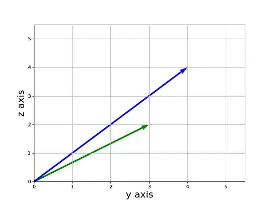
Then let's project the Green and Blue vectors into the $y=0$ plane by setting their y-coordinates to 0.
Note the axis labels. This is the oritentation you see if you're standing at the positive y axis. The signed area corresponding to this parallelogram is not
$$
det \left[
\color{green}{\left({\begin{matrix} 3 \\ 2 \end{matrix}}\right)}
\color{blue}{\left({\begin{matrix} 2 \\ 4 \end{matrix}}\right)}
\right]
$$
Rather, it's
$$
det \left[
\color{green}{\left({\begin{matrix} 2 \\ 3 \end{matrix}}\right)}
\color{blue}{\left({\begin{matrix} 4 \\ 2 \end{matrix}}\right)}
\right] =
- det \left[
\color{green}{\left({\begin{matrix} 3 \\ 2 \end{matrix}}\right)}
\color{blue}{\left({\begin{matrix} 2 \\ 4 \end{matrix}}\right)}
\right]
$$
That term on the right is the term from the cofactor expansion. The negative sign has to be there because the matrix $\left[
\color{green}{\left({\begin{matrix} 3 \\ 2 \end{matrix}}\right)}
\color{blue}{\left({\begin{matrix} 2 \\ 4 \end{matrix}}\right)}
\right]$ is reflected (swapped, inverted, mirror-image) from what you actually get when you project into $y = 0$.
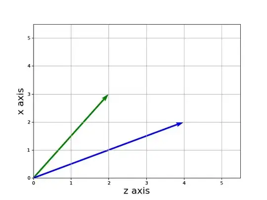
The following image shows the reflected (axes swapped) image of the projection which corresponds to the term in the cofactor expansion and necessitates having a negative sign in that term:

Again, note the axis labels. This is a reflection of what you see when you're standing on the positive y axis. In fact, it's what you would see if you were standing on the negative y axis. So we need to have a negative sign in the cofactor term that uses this "reflected" matrix of projected vectors.


