3

While searching for something very different, I stumbled upon these links by Emin Gabrielyan whom I assume is also the author of the arXiv preprint The basics of line moire patterns and optical speedup also in 2007.

The Examples of random moiré page contains the GIF below with the following description.

The figure below animates superposition of a base layer comprising randomly scattered copies of the symbol “2” with an opaque revealing layer comprising similarly placed tinny holes. In this animation, the revealing layer oscillates between –2 degree and +2 degree. The diameter of holes of this sample is about 4 to 5 times smaller than the size of the shapes of the base layer.

What's happening reminds me of some of the demonstrations of Tadashi Tokieda in the Numberphile video Freaky Dot Patterns, especially after 04:00.

How exactly does rotating one pattern ±2° relative to the other cause this huge zooming/de-zooming and inverting effect on the single big "2" in the center of the image?

from Examples of random moiré 2007-02-12 By Emin Gabrielyan https://docs.switzernet.com/people/emin-gabrielyan/070212-random-moire/

uhoh
  • 1,864

2 Answers2

5

Firstly let's try to clear things up by solving another case. Suppose we have a pattern on the complex plane and the patterns dimentions is P by P. Now suppose the function $B_1(x, y)$ gives us the inverted brightness of the point $x + iy$ the result is a number in $[0, 1]$ if it is black 1 and if white 0. Now Define $B_{1y}(x) = B_1(x, y)$. Now we want to make this function more easy to work with(smooth it) by deriving its Fourier series: $$ B_{1,k,y}(x) \approx A_0 + \sum_{n=1}^{k} (A_n \cos(\frac{2\pi nx}{P}) + B_n \sin(\frac{2\pi nx}{P})) $$ 
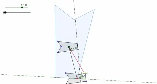
Now we rotate our pattern by $\theta$ radians by multiplying each point by the rotation matrix: $$ (x', y') = (x\cos\theta - y\sin\theta, x\sin\theta + y\cos\theta) $$ if now we put this pattern on a new plane and we define all the functions the same but instead of $B_1$ and $B_{1y}$ we have $B_2$ and $B_{2y}$ So now for this rotated pattern we have: $$ B_{2,k,y}(x) = B_1(x\cos\theta + y\sin\theta, y\cos\theta - x\sin\theta) = B_{1,k,y\cos\theta - x\sin\theta}(x\cos\theta + y\sin\theta) $$ substituting: $$B_{2,k,y}(x)\approx A_0 + \sum_{n=1}^{k} (A_n \cos(\frac{2\pi n(x\cos\theta + y\sin\theta)}{P}) + B_n \sin(\frac{2\pi n(x\cos\theta + y\sin\theta)}{P}))$$ Now if we put these two onto each other the inverted brightness at the point$(x, y)$ would be $max(B_1(x, y), B_2(x, y))$

Now for your case, the apparent brightness at each point would still be calculated this way but the second black page with dots would be modeled independently from the first page with one exception : the configuration of dots is like the "2"s. and we know that the "2"s are "the same shape" so with this in mind, let's make a "pattern" of only one "2". if we only have one "2" in our plane and our opaque sheet is rotating, the brightness of each point is derived the same way(keep this in mind for later). the position of each hole in the un-rotated opaque page is the position of each"2" on our stationary page. so if we invert the opaque page ($B_2$) and rotate it on our "2" page the total inverted brightness function is derived by: $$ B(x, y) = max(1-B_1(x\cos\theta + y\sin\theta, y\cos\theta - x\sin\theta), B_1(x, y)) $$
for small $\theta$ we have $\sin\theta \approx \theta$ and $\cos\theta \approx 1$ so here : $$ B(x, y) \approx max(1-B_1(x , y), B_1(x, y)) = 1 $$ which basically says if you put a sheet and its inverted verison you will get pitch black (logical)(here we don't have pitch black because the holes aren't exactly on the "2"s) but let's add a second term to each of our estimations: $$ \sin \theta \approx \theta - \frac{\theta^3}{6} $$ and $$ \cos \theta \approx 1 - \frac{\theta^2}{2} $$ so $$ B(x, y) = max(1-B_1(x(1 - \frac{\theta^2}{2}) + y(\theta - \frac{\theta^3}{6}), y(1 - \frac{\theta^2}{2}) - x(\theta - \frac{\theta^3}{6})), B_1(x, y)) $$ so this explains why a "2" appears when we have a small rotation: remember $B_{1,k,y}$ and $B_{2,k,y}$? well we know that the inverted opaque page has holes and its holes are at the positions of the "2"s so if we now modify our $B_{1y}$ and $B_{2y}$ such that $B_{1,k,y}$ has a sort of sine structure around the hole(at the hole $B_{1y}$ is maximum(1) and around it $B_{1,k,y}$ is a bit less than one) (we have smoothed it) and do the same with $B_{2,k,y}$ they will have a remarkably similar structure (one is the inverted of the other). This is exactly what we did with the fourier transform : if we set k at a sufficiently low number(1) we will have just a sine wave for both where the extrema's are equal. When we add the rotation of the opaque page for sufficiently low angles of rotation, since our pattern object ("2") is continuous and doesn't change drastically when we move a little on it, it is like we are transfering the sine wave to right or left and up or down (very little) and so the repeated object will more or less appear because the maximum and the minimum of our new rotated sine wave will(more or less) align with the stationary sine wave's maximum and minimum.(this is right or left) as the angle gets bigger there are two matters at hand: 1.the extrema of the rotated sine wave will line up with the extrema of the starionary sine waves which are above or below the mentioned sine wave. (up or down) this, combined with the (left or right) motion that we mentioned creates a spinning and magnifying effect(since with the increase of the angle, extrema line-up points end up farther from the center of rotation) 2. if the angle of rotation gets too large the estimation falls apart because then we can't neglect the rotation and estimate it as moving.

I'm NOT a native speaker sorry for bad english AND also it is my first ANSWER I hope it is acceptable.

  • 2
    this honestly is a new way -to my knowledge- though I belive by the sine wave it is better if you mention "just some smooth approximation", because it wouldn't best be modeled by sine waves but other than that I LOVED your approach. – Ilia Varnaseri Aug 09 '23 at 20:51
  • 1
    thanks! And yes I think that would have been a better way to describe it, although I think it would work with the fourier series that we mentioned though maybe we can set K to a larger number? anyways the approximation was the point! – StarbucksMediumCup Aug 09 '23 at 20:59
  • 1
    Welcome to Stack Exchange! What a wonderful first answer (I always love it when an answer unexpectedly moves to the complex plane to simplify the problem) :-) – uhoh Aug 09 '23 at 21:07
  • Both answers are really helpful so I'll bounty both. The Stack Exchange system requires the next bounty to be double of the first one (up to 500) so I (almost) always give the larger bounty to the user with lower reputation points. So have patience, I can award the 2nd bounty in 48 hours. Thanks again and Welcome to Stack Exchange! – uhoh Aug 11 '23 at 09:40
1

The GIF in the OP presents a rotating revealing layer over a static base layer. The revealing layer is black, and has random arrangement of pinholes. The base layer is white, with black figure 2's that are rotated by $\pi/2$. The figure 2's are placed in the same positions as the corresponding pinholes above.

Three questions come to mind:

  1. Why are we seeing the large figure "2" as a dark shadow across a twinkling star field?
  2. Why is the scaling changing with the rotation of the revealing layer?
  3. Why is the large "2" shadow apparently perpendicular to the figure
    2's in the base layer ?(this can be seen when the rotation reveals the base layer figures in the corners)

This answer sketches what's going on by looking at a specific case. General cases and proofs are left to the reader.

When the there is no rotation of the revealing layer, the pinholes lie directly over the corresponding figure 2's in the base layer. Assuming that the pinholes are actually "inside" their corresponding figures, the resulting composite image will be black. As we start to rotate the revealing layer, the pinholes will start to move to the "outside" of their corresponding layers. If we follow a given pinhole, it will turn white as it moves outside of its underlying figure, and then will begin "twinkling" black and white as it moves over non-corresponding figures. So we want to see how/when that transition from "inside" to "outside" occurs.

In the diagram below the figures on the base layer are concave pentagons, in the shape of the static gray pentagon. The large green dot inside that pentagon represents the unrotated corresponding pinhole. For our purposes we'll assume that it's at the center of the revealing layer - call it the "origin". The rightmost segment of that pentagon lies on a dashed black line. We'd like to know, for a given rotation, when it is that other pinholes transition from "inside" to "outside" their corresponding figures. It turns out, that for a rotation of angle $\theta$, any pinhole who's unrotated position is on the dashed green line will be on the border of its corresponding figure. The dashed green line can be calculated by applying a transform $T_{\theta}$ to the black dashed line. $T_{\theta}$ consists of a rotation of $-\pi/2-\theta/2$ and a scaling factor of $\dfrac{1}{2\sin(\theta/2)}$

In the diagram, $\theta=16°$, so the angle between the black and green dashed lines is $98°$. The light blue pentagon is the result of applying $T_{\theta}$ to the static pentagon.

The animation shows a variable pinhole (the hollow red point) moving along the boundary of the light blue pentagon. The solid red point shows the pinhole rotated by $\theta$. Note the red point moves along the border of its corresponding base layer figure. Pinholes whose unrotated position is inside the light blue pentagon will still be inside their corresponding base layer figures after a rotation of $\theta$, while pinholes starting outside of the light blue pentagon will be outside of their corresponding figures.

The upshot of this is that the light blue pentagon is the dark moiré region observed in the OP. It will scale and rotate according to $T_{\theta}$ as the revealing layer rotates. For negative $\theta$ it will invert. Finally, for small $\theta$ the moiré region will appear to be perpendicular to the base layer figures, but this is only approximately true.

For a more comprehensive exposition see also Amidror, Moiré patterns between aperiodic layers: quantitative analysis and synthesis (2003) in particular Fig. 2 and Section 4.B (Case 1).

brainjam
  • 8,626
  • @uhoh thanks for your generous bountie(s). This was a great question, and before I sat down to work out the geometry I implemented my own web version at https://codepen.io/brainjam/pen/oNQOXGQ . Viewed on a laptop, the main code is in the "JS" box at the bottom left and you can fiddle with it, including changing the 'π' in the second last line to other characters. – brainjam Aug 11 '23 at 23:04