General approach
Your deformation looks like a projective transformation. Since projective transformations preserve neither angles nor lengths nor even length ratios, your attempts using elementary trigonometry are probably bound to fail. A projective transformation in the plane is uniquely defined by four points and their images, as long as no three points lie on a common line. This answer gives details on how you can compute such a transformation.
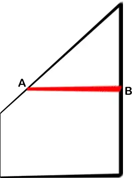
Note that if you already know the coordinates of the “pulled” rectangle corner ($E$ in your question), then you can simply use your four corners as the four defining points. Since finding the correct position for $E$ is non-trivial, I didn't make that assumption. So the main task here is finding four suitable pairs of points. You can use the resulting machinery not only without prior knowledge of $E$, but in fact even as a tool to compute $E$ in the first place.
Coordinates for four defining points
Suppose your original rectangle has width $w$ and height $h$. Then you can assume the following homogenous coordinates. I'll place the origin of the coordinate system in the lower left corner of your rectangle, and the positive $y$ axis pointing upwards. If you use a different convention, these coordinates should be easy to adapt.
\begin{align*}
P_1 &= \begin{pmatrix}0\\0\\1\end{pmatrix} &
P_2 &= \begin{pmatrix}w\\0\\1\end{pmatrix} &
P_3 &= \begin{pmatrix}w\\h\\1\end{pmatrix} &
P_4 &= \begin{pmatrix}0\\h\\1\end{pmatrix} \\
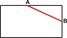
A &= \begin{pmatrix}a\\h\\1\end{pmatrix} &
B &= \begin{pmatrix}w\\b\\1\end{pmatrix} &
H &= \begin{pmatrix}1\\0\\0\end{pmatrix} &
V &= \begin{pmatrix}0\\1\\0\end{pmatrix} &
\end{align*}
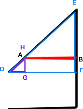
The points $P_i$ are the corners of your rectangle, $A$ and $B$ are as in your images, while $H$ and $V$ are the points at infinity through which all horizontal resp. vertical lines must pass. Now we need some additional points. Using homogenous coordinates, you can use the cross product to express both the line joining two points and the point at the intersection oftwo lines. So the line $AB$ will intersect the bottom line of your rectangle in a point
$$Q = (A\times B)\times(P_1\times P_2)$$
Now you can define your transformation using the following:
\begin{align*}
P_1 &\mapsto P_1 \\
P_2 &\mapsto P_2 \\
P_4 &\mapsto P_4 \\
V &\mapsto V \\
Q &\mapsto H
\end{align*}
So three corners remain where they are, vertical lines remain vertical, and the two lines intersecting at $Q$ will both become horizontal. These are five points, not four, but some of them are collinear. So I'd keep the first three conditions, and use some point constructed from several of these defining points as the fourth condition:
$$ (P_2\times V)\times(P_4\times Q) \mapsto
(P_2\times V)\times(P_4\times H) $$
This gives you a fourth defining pair of points which (barring degenerate situations) does not lie on the same line as two of the other defining points. So now you have four pairs of preimage and image points, and can compute the transformation matrix from these.
Using the transformation
Applying that transformation matrix to $A$ or $B$ (and perhaps $P_3$) will give you their new coordinates, which you'll probably want to dehomogenize. But these steps are also described in my other post.
Explicit result
All of the above computations could be done symbolically using some computer algebra system. the resulting expressions aren't that bad. The $y$ coordinate of $E=P_3'$ is
$$E_y = \frac{a\,b\,h-w\,h^2}{a\,b-b\,w}$$
and the $y$ coordinate of the transformed line $AB$ is
$$H_y = \frac{a\,b-h\,w}{a-w}$$
So if you only need these, but need them in a number of situations, then you might simply want to implement this final formula. Understanding the whole process used to obtain these will however be useful in dealing with other, similar situations.
Sage code
I obtained the above formulas using the following piece of sage code:
def joinMeet(a, b, c, d):
    return a.cross_product(b).cross_product(c.cross_product(d))
def pm1(a, b, c, d):
    M = Matrix([a , b, c]).transpose()
    f = M.solve_right(d)
    return M*diagonal_matrix(f)
def pm(a1, a2, b1, b2, c1, c2, d1, d2):
    return pm1(a2, b2, c2, d2)*(pm1(a1, b1, c1, d1).adjoint())
def dehom(p):
    return vector([p[0]/p[2], p[1]/p[2]])
var('w h a b')
P1 = vector([0, 0, 1])
P2 = vector([w, 0, 1])
P3 = vector([w, h, 1])
P4 = vector([0, h, 1])
A = vector([a, h, 1])
B = vector([w, b, 1])
H = vector([1, 0, 0])
V = vector([0, 1, 0])
Q = joinMeet(A, B, P1, P2)
R1 = joinMeet(P2, V, P4, Q)
R2 = joinMeet(P2, V, P4, H)
M = pm(P1, P1, P2, P2, P4, P4, R1, R2)
print(dehom(M*P3)[1].simplify_full())
print(dehom(M*A)[1].simplify_full())