1

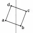
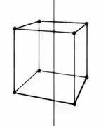
I have seen so many mathematical procedures including matrix. But all don't seem to plot a perspective view. Why is it hard to establish simple vector equations by which you can input the true x,y,z coordinates of any point in the object and output X,Y coordinates of the corresponding point in perspective projection? Keep in mind that the perspective view is such as a photo taken by a camera. Hence, the location of the camera with respect to the object as well as the tilt angle of the camera (as per bird's and worm's eye views) can give different perspective views. Does anyone have any mathematical approach to execute such a process? Coordinates of the plan a(-0.38, 1.86). b(0.18, 1.65) c(0.38, 2.21). d(-0.18, 2.41) The height of the cube is (0.61) Please, show me how you get the coordinates of eight points of the perspective drawing. Thanks!

plan of a cube

perspective of a cube

  • 1
    Related : http://math.stackexchange.com/questions/1216298/how-to-calculate-true-lengths-from-perspective-projection – Watson Mar 05 '16 at 10:19
  • 1
    the frustrum type perspective is simple : rotate the object so that it is in front of the camera, and draw each point $(x,y,z)$ at $(\alpha x/z,\alpha x/z)$ on the screen – reuns Mar 05 '16 at 10:19
  • Thanks, I don't understand it. Why can't you show me practically how it's applied to a cube. By considering a plan of the cube (a square rotated at any angle) then finding the corresponding eight points of the perspective drawing of the cube. Try to show me the coordinates of the eight points so that I can plot them on paper. – Dhirgham Murran Mar 06 '16 at 18:26
  • It doesn't matter how accurate the measurements. Let it be tall or short cube. I just measured them by ruler. The camera is above the top of the cube. You can assume any height bigger than 0.61. Let it be (1). All I like to know (how do you get the vertices of the perspective drawing from the plane coordinates). The relation must be clearly shown by vector equations. Thanks.... – Dhirgham Murran Mar 07 '16 at 17:24
  • This is explained in computer graphics textbooks. (Or in computer vision textbooks that discuss "camera matrices".) The projection equations ate nonlinear, but they can be expressed nicely with matrix notation if we use "homogeneous coordinates". – littleO Mar 08 '16 at 16:16

3 Answers3

3

Imagine a central projection, with $(0,0,0)$ as the center and $z=1$ as the image plane. Then you draw a 3D point $(x,y,z)$ at position $(x/z,y/z)$. That's the core idea behind homogeneous coordinates: any point in the direction $(x,y,1)$, i.e. any multiple thereof, represents the point $(x,y)$.

If your camera or your image plane is somewhere else, you'd usually first apply a transformation to reduce that to the situation just described. If you want to include translations in 3d space, you would input homogeneous 3d points, i.e. vectors with four elements, so the whole projection would be a $3\times4$ matrix converting homogeneous input to homogeneous output coordinates.

MvG
  • 42,596
  • Thanks, I don't understand it. Why can't you show me practically how it's applied to a cube. By considering a plan of the cube (a square rotated at any angle) then finding the corresponding eight points of the perspective drawing of the cube. Try to show me the coordinates of the eight points so that I can plot them on paper. – Dhirgham Murran Mar 06 '16 at 18:22
  • Here's a simple solution, based on trigonometric vector equations. [1]: https://m.youtube.com/watch?v=g3ot1nQaV_c – Dhirgham Murran Jul 23 '16 at 15:12
0

Since you are not so fussy i'm resolving the ambiguities to the point where we have concrete 'simple vector equations' such as $x=PX$, to produce the $8$ coordinates of the perspective drawing.
As $3$D points let's choose: $$AT = (-0.380, +1.860, +0.305)^t\\ BT = (+0.180, +1.650, +0.305)^t\\ CT = (+0.380, +2.210, +0.305)^t\\ DT = (-0.180, +2.410, +0.305)^t\\$$ for the top and enter image description here $$AB = (-0.380, +1.860, -0.305)^t\\ BB = (+0.180, +1.650, -0.305)^t\\ CB = (+0.380, +2.210, -0.305)^t\\ DB = (-0.180, +2.410, -0.305)^t\\$$ for the bottom.

For the $2$D projections i manually extracted them from the perspective drawing showing the $8$ points. These are given in so called pixel coordinates. Since your image has the size width$~=144$ and height$~=178$, they don't exceed those values. Please don't use .jpg for line drawings: use .png$$ at = (021.45, 041.01)^t\\ bt = (106.13, 047.19)^t\\ ct = (124.18, 034.18)^t\\ dt = (056.27, 030.27)^t\\$$ for the top and $$ ab = (021.02, 130.82)^t\\ bb = (106.56, 148.07)^t\\ cb = (124.18, 110.32)^t\\ db = (056.27, 099.91)^t\\$$for the bottom.

Now we follow the procedure from here for a way to fit a projection matrix $P$ to $2$D and $3$D point correspondences.enter image description here

Blue circles $at, bt, \ldots$, magenta stars: projections of $AT, BT, \ldots$ $$P=\begin{pmatrix} 136.11 & -01.54 & +000.00 & 080.14\\ 001.42 & -42.17 & -137.89 & 165.94\\ 000.00 & +00.00 & +000.00 & 001.00 \end{pmatrix}$$

  • Practically you extracted the perspective points from the drawing itself. But, the question is how you can define those points if you don't have the perspective drawing. How can you establish the points of the perspective projection from the plan points AT,BT,AB,BB, etc. – Dhirgham Murran Mar 08 '16 at 17:53
  • I am not familiar with the matrix of numbers. How can you solve it. Sorry to be a pain. – Dhirgham Murran Mar 08 '16 at 18:36
  • Here's a simple alternative dragon – Dhirgham Murran Jul 23 '16 at 19:49
  • Here's a simple solution, based on trigonometric vector equations. https://m.youtube.com/watch?feature=youtu.be&v=g3ot1nQaV_c – Dhirgham Murran Jul 23 '16 at 19:56
0

3D perspective vector formulas Perspective equations

I am the founder of these equations. They were the source code of a perspective machine patented in 1981 in England (Patent No. GB-2069938A). I was 19 years old when I invented it. These equations are the only simple vector equations that define the perspective projections of any object rotating in any direction. The equations also involve the zoom factor (F) and the tilt angle of the camera (n°) to plot bird's-eye and worm's-eye views. You only have to input x,y,z coordinates of any object to get the perspective projection coordinates (X and Y). The equations are easy to prove, but the diagram is based on three point perspective procedure which is hard to understand. There isn't a lot of resources to clarify three point perspective except in my book. I put them publicly for sake of the community in large if they serve the purpose for descriptive geometry for 3D-CAD software development. I will be pleased to answer any of your questions. Here you can find the complete research and the proof of the above equations:

https://www.quora.com/What-is-the-simplest-mathematics-to-generate-3D-models/answer/Dhirgham-Murran-1

I also put on Google Drive the Excel file, by which you can input (x,y,z) coordinates together with the tilt angle of the camera (n) and the magnification constant (i.e. zoom in/out "F") and the output perspective coordinates (X,Y) will be automatically given based on the equations.

https://drive.google.com/file/d/14fczx3h4TosEAYVCuJ9reCpEIqPGb_9y/view?usp=drivesdk