2

I worked with matrices of translation, rotation, scale but the perspective one is new for me.

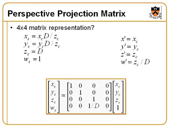
Could you explain why there are a lot of examples of perspective matrices with various values inside? For example I like this easy one:

http://www.cs.princeton.edu/courses/archive/fall99/cs426/lectures/view/img029.gif

But google shows some awful examples, for example:

http://ogldev.atspace.co.uk/www/tutorial12/12_11.png

Could you explain how to convert from one type to another?

iadvd
  • 8,875

2 Answers2

4

Projective transformations in general

Projective transformation matrices work on homogeneous coordinates. So the transformation

$$\begin{bmatrix} a & b & c & d \\ e & f & g & h \\ i & j & k & l \\ m & n & o & p \end{bmatrix}\cdot\begin{bmatrix} x \\ y \\ z \\ 1 \end{bmatrix} = \lambda\begin{bmatrix} x' \\ y' \\ z' \\ 1 \end{bmatrix}$$

actually means

$$\begin{bmatrix}x\\y\\z\end{bmatrix}\mapsto\frac1{mx+ny+oz+p}\begin{bmatrix} ax+by+cz+d \\ ex+fy+gz+h \\ ix+jy+kz+l \end{bmatrix}$$

so compared to linear transformations you gain the power to express translation and division.

Just like with linear transformations you get the inverse operation by computing the inverse matrix. Unlike affine transformations, a multiple of the matrix will describe the same operation, so you can in fact compute the adjunct to describe the inverse transformation. Then you plug in the points $(±1, ±1, ±1, 1)$ and apply that inverse transformation in order to obtain the corners of your frustrum in view coordinates.

This post describes how you can find a projective transformation if you know the images of five points in space, no four of which lie on a common plane.

Your perspective transformations

There are two ways to understand your perspective transformations. One is by computing the coordinates of the corners of the frustrum, the other by investigating the structure of the matrix. I'll leave the former as an excercise, and follow the latter.

The first example you quote has its geometrix effect already denoted in the upper left corner. You can think about this as two distinct steps. In the first step, the vector $(x,y,z)$ is divided by $z$. This means you're projecting your line of sight onto the plane $z=1$. Afterwards, everything is scaled by $D$ in the $x,y,z$ directions. So you have a plane of fixed depth somewhere in your image space. Which is of little use in case you want to do something like depth comparisons.

The second example appears to be the standard OpenGL perspective projection, as implemented by gluPerspective, except for some sign changes. This doesn't map everything to the same depth, but instead maps the range between NearZ and FarZ to the interval $[-1,1]$. The new $(x',y')$ coordinates, on the other hand, are essentially the old $(x,y)$ coordinates, divided by $z$ to effect a projection onto the image plane, followed by a scaling which depends on an angle $\alpha$ denoting the field of view. The scaling also takes a factor ar into account, which denotes the aspect ratio.
MvG
  • 42,596
  • Excellent explanation; I like how you included the idea of how OpenGL uses this as their basis for creating a view frustum. I remember having to implement my own in legacy OpenGL 1.0. Now we have Shaders in modern OpenGL :), and creating a view frustum went from about 50 - 100 lines of code to write a function or a small to medium size class to just a few lines of codes of calling OpenGL's API calls, setting a few parameters and doing a couple of calculations bases on your screen's resolution, color scheme and window's size of the application. I give you two thumbs up! ... – Francis Cugler Jan 10 '17 at 20:48
  • (...continued) I learned this from this book : 3D Game Design (2E) by David H. Eberly found here: https://www.geometrictools.com/Books/Books.html as well as other various sources of research. – Francis Cugler Jan 10 '17 at 20:51
0

The "easy" one is the perspective divide in matrix form, which has to follow the "awful" one.

The "easy" matrix shows the right column starting with $x' = x_c$. x, y and z all have identity; only w is z/D. But with contradicting indices (s, c, slash) and an undefined D (for depth?) I don't see much sense in this matrix. The thing itself - divide by z - is important, of course.

The complicated (real) perspective matrix has a "1" on the bottom row. This stores the z value aka depth into the w coordinate, while the x, y and z get scaled into clip space, according to the angle of view and the near and far planes.

But the division by z can't be coded in a matrix. This perspective divide is done afterwards. Maybe the "easy" matrix is for this step, but it seems overkill. The perspective divide is

$x_{ndc} = x_{clip} / w_{clip}$

and same for y and z. No need for a matrix, only the z value saved into the w coordinate by the perspective matrix. In OpenGl the variable gl_FragCoord holds the current x, y and z values ie. NDC scaled to window size (for x and y) or depth range (for x). The 4th coordinate contains 1/w. The "easy" matrix would make more sense with a $w_s = 1 / z_c$. Dividing $w_c$ by itself would be just another way to say "1".

So the "google" matrix does the perspective projection of a geometric frustum into a normalized cube, but minus the final division, which is only prepared.

It is not a question of converting, but of doing the second first and then replacing the first with a simple perspective divide.

neslrac
  • 185