1

I'm trying to use a RaspberryPi3 as a FM transmitter, using pifm and/or PiFmRds to send audio in 88-108 MHz band. The RPi can then use the GPIO-4 pin to transmit between 1-250 MHz. However, nobody want to ruin their HW while still optimizing the output by using a proper antenna.

  1. What is the best antenna design to use? (A wire, dipole or something else?)
  2. How to best connect the antenna? (I.e. Do we need impedance matching?)

I would like to avoid any amplifiers or extra active hardware.

EDIT-1:

  1. I'm of course fully aware of the legalities of TX on FM band.
  2. Apparently the RPi GPIO impedance is around 30-60 Ohms.
  3. This is an antenna problem, because the question is equally valid for any transmitter.
  4. The best options I have seen so far is this FM loop or this quad loop...
not2qubit
  • 378
  • 5
  • 16
  • You'll probably get more relevant answers at http://raspberrypi.stackexchange.com. – Phil Frost - W8II Mar 15 '17 at 22:41
  • 1
    @PhilFrost-W8II Hardly, since this is an antenna question. – not2qubit Mar 16 '17 at 01:10
  • How to protect the GPIO of a Raspberry Pi is not an antenna question. – Phil Frost - W8II Mar 16 '17 at 01:27
  • You are best off asking this type of question in the pi stack because they are the ones who are more likely to know for instance the actual impedance of the pins you want to use. There is no "best" type of antenna, it is all dependent on what you intend to use the transmitter for how much power is involved and what type of receiver you intend to use. If you are in the USA you can't legally transmit on those frequencies without a license unless your transmission can not be heard beyond 200 ft. You are responsible for being in compliance of that. If you are not the fine is $10,000 per day. – Rowan Hawkins Mar 16 '17 at 02:03
  • I'd also suggest that you stay off frequencies above 108 megahertz to 250 megahertz. That falls squarely in the middle of aeronautical and navigation bands and those people really don't play around if you start affecting their stuff. – Rowan Hawkins Mar 16 '17 at 02:11
  • 1
    I don't agree. Just imagine the question without "RPi" being mentioned at all. Still same antenna and frequency. Also I specifically said no extram amps etc. which means that it's probably well within global legal range of a few mW. – not2qubit Mar 16 '17 at 04:12
  • Possible duplicate of: http://ham.stackexchange.com/questions/7267/is-it-legal-to-broadcast-an-fm-radio-signal-with-a-raspberry-pi-zero/7278#7278 – hotpaw2 Mar 16 '17 at 05:01
  • 1
    @not2qubit If you want the question without "RPi", then edit it so it doesn't say "RPi". People aren't going to imagine the question to be something other than what it is. – Phil Frost - W8II Mar 17 '17 at 12:38
  • 2
    You might also want to explain why the antenna instructions in the pifm README don't answer your question. – Phil Frost - W8II Mar 17 '17 at 12:39
  • To expand upon the question: As a required subset of "best connect": Is it possible to wire up an antenna so reactive that it would damage a CMOS level SoC digital output? If so, what kinds of general antenna and feed configurations should be avoided to prevent this? – hotpaw2 Mar 18 '17 at 05:55
  • I've edited the title. A 20 cm wire antenna can't possibly be as efficient as, for example, the ones I've linked. However, if I choose to use such a big antenna, I'd be quite worried about some sort of back-feed or ESD that could zap the GPIO (as it was never meant to do this.) How could that be prevented? – not2qubit Mar 18 '17 at 05:56
  • @hotpaw2 You answered at the same time! Yes, that is the kind of question I'm looking for an answer to. – not2qubit Mar 18 '17 at 05:57
  • FYI, here are two articles that relate to transmitting with the Pi: http://qrznow.com/transmitting-fm-am-ssb-sstv-and-fsq-with-just-a-raspberry-pi/ and http://www.rtl-sdr.com/transmitting-fm-am-ssb-sstv-and-fsq-with-just-a-raspberry-pi/ – SDsolar Apr 09 '17 at 21:14

2 Answers2

3

To be legal, you will need a low-pass or FM band-pass filter between the Pi's digital output and any antenna. Otherwise, the antenna will also be transmitting at a bunch of harmonic frequencies well outside your intended band (into multiple higher frequency bands at 2X, 3X, 4X, 5X, etc. your intended FM frequency.)

Added: This is because periodic digital waveforms (produced by digital IO pins) contain lots of energy at lots of harmonic frequencies (Fourier's theorem).

Also, see this question: Super-low-tech VHF low-pass filter construction?

Added #2: Given that the current output of a Pi's 3.3V GPIO pin is recommended to be kept below somewhere between 3 mA to 16 mA (depending on how many other GPIO outputs are being used), an impedance (resistor or ?) of somewhere in the range of 220 Ohms to 1.5k Ohms might be required somewhere in the matching network between the output and a 50 Ohm antenna load.

hotpaw2
  • 13,316
  • 6
  • 45
  • 76
  • This doesn't really answer the question, which is about matching to a suitable antenna. (Which could even incorporate a filter!) – Kevin Reid AG6YO Mar 18 '17 at 16:09
  • I interpret "best" to include "legal". And, yes, a proper (legal) filter could also include a proper match. – hotpaw2 Mar 18 '17 at 16:45
  • Yes, but you don't at all answer the aspects of matching and antenna design which were actually asked about. This answer is incomplete. – Kevin Reid AG6YO Mar 18 '17 at 17:29
1

After some further research, I've decided to answer my own questions as I find the current answers insufficient. Evidently the "best" antenna also seem to be the simplest.

From the article: "Antenna 101: Let’s Review the Basics" by Dan Farber (AC0LW) in the magazine The Spectrum Monitor [July, 2016].

Consider once again the humble dipole. In its most basic form, it is cut to resonance at a desired frequency in a single band, and fed with coaxial cable. Notice that one side of the dipole is thus connected to the coax’s shield. Down at the radio end, the coax shield is connected to RF ground, that is to say the grounded side of the coax connector. This works fine with no additional RF grounding.

This and the well known fact that the impedance of a:

  • 1/4-wave vertical with good RF ground is ~35 Ohms.
  • 1/2-wave dipole is ~70 Ohms.

This matches very well with the GPIO impedance that is believed to be somewhere between 30-60 Ohms. (How to test?) Thus we can expect a natural impedance matching, or at least close enough, which is probably why these simple wire antennas work so well.

So as noted by the commenters in this link, a simple 1/4-wave wire with a 1/4-wave ground along the table, will be quite efficient. The wires also has to be electrically isolated, to help prevent possible static damage.

How to best prevent GPIO ESD damage?

There are several ways applicable here:

  1. Use a ESD/TSV chip such as the TPD1E01B04 with Cio=0.2 pF.
  2. Use a simple resistor with R >= 100 K Ohms.
  3. Use an inductor or inductive coil with X >= 100K @ 100 MHz.

In each case you should connect the part between the antenna wire and device GND. Please see THIS excellent blog about how to prevent static and lightning damage.

WARNING I now recommend against using an inductor only, as it would force ground the GPIO pin, if set to 1 at DC during any other time, before the HF has been activated. This would surely damage your RPi.

A simple band-pass filter

The construction of a passive Band Pass Filter can be seen HERE and another filter is very nicely described HERE. In the video he uses the following values, but can probably be tuned even more.

Cgnd = 10 pF
Cio  = 2.2 pF
Rgnd = 1 K 

passive Band Pass Filter

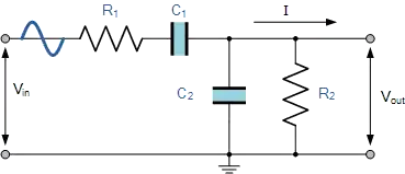
(Same as in video, if R1 is removed.)

To amplify the GPIO signals

Please look at THESE RPi GPIO driver aspects.

NOTE-1: For those concerned about the transmitted power, I've estimated it to be about 0.37 mW in THIS answer.

EDIT-1: I've found a few more excellent resources that explains exactly how this should be done.

The first one is: QRPi - A Raspberry Pi QRP TX Shield Design, from where:

However there were still one thing missing: no buffer stage to protect the BCM2835 SoC's clock generator output stage. Hardware failure due to the unbuffered operation of the WsprryPi program was reported by a few HAM operators, possibly due to overload from nearly broadcast transmitter stations. If buffer amplifier was already needed it was a good idea to add some gain to the system. Eventually using a single FET amplifier stage [fig 7] 10 dB gain achieved, delivering +20 dBm output power at the end of the LPF [fig 4]... For ESD and static discharge protection an ESD suppressor diode was added to the antenna terminal of the circuit.

The other ones are:

There are several great links to filter, amplifier and buffer designs there. In addition, a simple design can allow you to transmit in the 20m HAM band several thousands of kilometers. Amazing.

The GitHub README from the last link, basically concludes all my original questions:

As the Raspberry Pi does not attenuate ripple and noise components from the 5V USB power supply, it is RECOMMENDED to use a regulated supply that has sufficient ripple supression. Supply ripple might be seen as mixing products products centered around the transmit carrier typically at 100/120Hz.

DO NOT expose GPIO4 to voltages or currents that are above the specified Absolute Maximum limits. GPIO4 outputs a digital clock in 3V3 logic, with a maximum current of 16mA. As there is no current protection available and a DC component of 1.6V, DO NOT short-circuit or place a resistive (dummy) load straight on the GPIO4 pin, as it may draw too much current. Instead, use a
decoupling capacitor to remove DC component when connecting the output dummy loads, transformers, antennas, etc. DO NOT expose GPIO4 to electro- static voltages or voltages exceeding the 0 to 3.3V logic range; connecting an antenna directly to GPIO4 may damage your RPi due to transient voltages such as lightning or static buildup as well as RF from other transmitters operating into nearby antennas. Therefore it is RECOMMENDED to add some form of isolation, e.g. by using a RF transformer, a simple buffer/driver/PA stage, two schottky small signal diodes back to back.

not2qubit
  • 378
  • 5
  • 16