11

I'm looking for a simple way to impedance match an array of two 50 Ω antennas so that when they are combined they appear as one 50 Ω load.

Assume that both antennas are identically constructed, are in phase with one another, and have the same VSWR very close to 1. The frequency the antennas are tuned to is 2.4 GHz.

Is there a simple “rule of thumb” method that I could use that requires little equipment?

Kevin Reid AG6YO
  • 24,506
  • 7
  • 51
  • 103
Ben
  • 347
  • 2
  • 7
  • I'm Marthien I'm interesting for this answer make me have a some idea. my question is what if the combine antena is different, like the antena cable delta loop 40m and dipole tubing aluminum 40m ? and what if i must combine three antena with the different band like 20m + 15m + 10M ? thanks before for the answer. best regard YB1BBW-Marthien – marthien tarihoran Oct 04 '22 at 01:08
  • 1
    @marthientarihoran It's the feedpoint impedance of the antenna that matters, so if they are each a good 50Ω match separately at the same frequency it shouldn't matter if they are different in other ways. As to your three-antenna question that's discussed a bit in the comments below https://ham.stackexchange.com/questions/1764/how-to-combine-two-50-%ce%a9-antennas-such-that-they-appear-as-one-50-%ce%a9-load#comment2121_1768 but the antennas you ask about are not used at the same frequency. You should open a new question e.g. "can I feed multiple different band antennas with one coax?" – natevw - AF7TB Oct 04 '22 at 20:04

1 Answers1

10

The canonical solution to this problem is a Wilkinson power divider. There are of course other power dividers, but the Wilkinson is easy to fabricate, provides good isolation between the output ports, and is lossless when the output ports are equal and in phase, which is true for an ideal antenna array.

If you were to make one of these yourself, you'd probably do it with coax. However, it's easier to illustrate with microstrip:

microstrip power divider

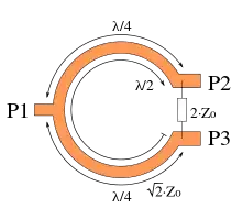
P1 would be connected to your transmitter, and P2 and P3 to your antennas.

Between P1 and P2, and also between P1 and P3, are quarter-wavelength transmission lines having an impedance of $\sqrt 2 \cdot Z_0$. For your case that works out to $\sqrt 2 \cdot 50 \Omega = 70.7\Omega $. 75 ohm coax is close enough and easier to find.

Between P2 and P3 is a resistor that's twice the characteristic impedance. For your case, that's $100\Omega$.

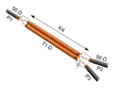
Made with coax, it looks something like this (click for bigger version):

coax power divider

Although it's not impossible to fabricate this sort of thing yourself, doing so at 2.4 GHz is a bit of a trick, especially if you don't have test equipment. 2.4 GHz is a very popular band, and this is a very common device, so you won't have any difficulty finding a pre-made solution for purchase.

Phil Frost - W8II
  • 51,701
  • 6
  • 88
  • 212