14

An easy TDOA design by Byonics was published with the following schematic:

Two dipole antennas with a diode switcher controlled by a microcontroller feeding a radio

It appears that the antennas are switched at a rate of 640Hz, which allows a 640Hz tone to be heard in the radio when the antennas are not in phase. When the antennas are equidistant from the RF source, the tone goes away, so by turning the antenna and finding the null you can determine the direction of the source.

The author's description further explains:

Note that the transmitter being on that perpendicular line means that it could either be directly ahead, or directly behind. You would need to move some distance along the line of the antennas and take another bearing to determine which direction the transmitter actually was. In the next version, when the audio from the receiver is fed back into the chip and analyzed, it will be able to tell if the signal is coming from the left or right when the tone is present, and light the appropriate LED. (emphasis added)

With the radio's audio going into the microcontroller, and the antennas out of phase with the source, what is the microcontroller looking for, or how would it tell, whether the signal is coming from the right or the left of the dipole array?

Kevin Reid AG6YO
  • 24,506
  • 7
  • 51
  • 103
Adam Davis
  • 12,125
  • 2
  • 47
  • 107
  • Page 26 of this technical article on Doppler direction finding also answers this question: http://www.cvarc.org/new-wp/download/technical/t-hunting_and_doppler_df.pdf – Adam Davis Jul 24 '14 at 23:49
  • The good old "Double Ducky Direction Finder". Very similar to a pseudo-doppler. It neither knows or cares what the absolute phase is, only the difference. And it can't discriminate a signal behind you from one in front of you. A pseudo-doppler can. – user103218 Jan 02 '20 at 22:53

1 Answers1

17

When the tone is present, it is because the antennas are out of phase. One antenna's signal will be leading the other; which one is leading depends on which one is closer to the transmitter (provided that the antennas are less than 1/2 wavelength apart, so that the phase difference will always be less than 180°).

When we switch from the lagging signal to the leading signal (for example), the phase of the switched signal jumps ahead; equivalently, the frequency of the signal increases for an instant and then returns to normal. The same but inverted applies to switching from the leading signal to a lagging signal. The output of a FM receiver is determined by the frequency of the input, so we get a result like this:

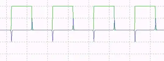
The green waveform is the switch control and the blue waveform is the demodulated signal (the frequency deviation). After audio-frequency filtering on the output, we get a more ordinary tone, though with a delay introduced by the filter:

If the time delays of the arriving signal are the other way around, then the phase shifts are opposite, and the audio signal is negated — or, equivalently, phase shifted by 180°.

Therefore, to distinguish between left and right (that is, left signal leading vs. right signal leading) one need merely compare the phase of the audio signal to the phase of the switching signal; there are only two possible results (except when the audio tone is absent and the phase is therefore undefined).

Note that the exact phase difference found will depend on all delays in the system, including in the external receiver; but that would be simple to calibrate for.


I have built a simulation of this system using GNU Radio, and used it to produce the plots shown and confirm that the technique can produce a reliable left/right indication (at least for an unmodulated input). Here are the GNU Radio Companion file and generated Python program (GNU Radio 3.7+ required).

enter image description here

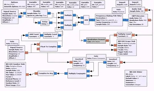
Note that while the RF sections of this simulation use complex (analytic) signals, there is nothing in those sections which would make a difference from the results obtained by using real signals at a nonzero IF as usual analog RF electronics do.


On the other hand, in the perpendicular direction, it is not possible to distinguish the front and back sides; there is a fundamental ambiguity due to the symmetry of the antenna array. No direction finding system can distinguish between directions in which its antennas are symmetrical; the asymmetry which allows the discrimination described here comes from the switching of the antennas rather than their shape.

Kevin Reid AG6YO
  • 24,506
  • 7
  • 51
  • 103
  • 1
    Interesting. FM reception is basically phase modulated, so you're introducing the tone by modulating the phase using antenna switching. It wouldn't work with an AM, CW, or SSB foxhunt - at least not as cleanly as a 640Hz tone. But I think you're correct that it's important the antennas are less than 1/2 wavelength apart, thus one will be leading the other, and the one that's leading is closer. The FM demodulated tone generated from this would have the appearance of a square wave that decreases in amplitude the closer these are in phase. I'm tempted to build it just so I can scope it... – Adam Davis Mar 14 '14 at 19:04
  • 1
    @AdamDavis I think it would work for AM, CW, or SSB, provided you still have an FM receiver. If you modulate the phase of any of those signals, an FM receiver still hears it as a tone. It might even work better, as when you are receiving FM with this device, you will hear the tone added to the baseband signal, but when receiving AM, CW, or SSB, there is 0 frequency deviation, so the tone must compete only with atmospheric noise. – Phil Frost - W8II Apr 04 '14 at 11:26
  • I'm not really sure this explanation works. Neglecting limits on bandwidth imposed by filtering, the baseband signal coming out of this thing looks like a square wave. Say when it switches from antenna A to B, that's the rising edge. You are saying you could know the direction by looking at whether we are rising or falling at the time of that switch. However, walk away from the transmitter half a wavelength, and now switching from A to B gives you a falling edge. – Phil Frost - W8II Apr 04 '14 at 11:43
  • 1
    @PhilFrost "I think it would work for AM, CW, or SSB, provided you still have an FM receiver." Good point. – Adam Davis Apr 04 '14 at 12:20
  • 1
    @PhilFrost Moving away half a wavelength is equivalent to going back in time half a period, so that part can't be relevant. As to the rest of it, I think I'll test my explanation by building a simulation, if I find the spare time. – Kevin Reid AG6YO Apr 04 '14 at 15:35
  • 1
    @PhilFrost I've built the simulation and confirmed it works. Yes, the output viewed at baseband has the shape of a square wave, but it's switching between two phases, which have a stable relationship with the phase of the switching signal. (I'd like to include an illustration of this, but it would require an animation, which I haven't got tools handy to make.) – Kevin Reid AG6YO Apr 05 '14 at 20:57
  • 2
    I see it now. The phases aren't relevant -- the change in phase is. Thanks for the images! – Phil Frost - W8II Apr 06 '14 at 11:55