1

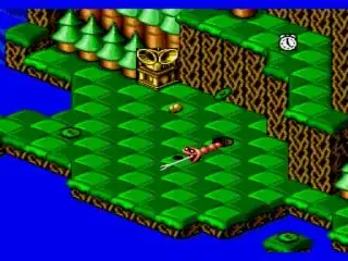
I'm trying to render isometric maps, my final goal is to render scenes that resembles Snake Rattle 'n' Roll:


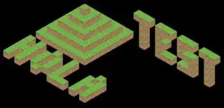
So I started by rendering cubes:


For now I have an array with a collection of 3D vectors with integer components (sf::Vector3<std::size_t>) (no cubes located on half tiles) and I am brute forcing each cube position by multiplying that position by how much each cube should be displaced in each axis. Sorry for my poor communication skills, I hope that the code explains itself:

template <auto degrees>
constexpr auto degrees_to_radians_v = degrees * std::numbers::pi_v<decltype(degrees)> / decltype(degrees){180};

constexpr auto radians_60dg = degrees_to_radians_v<60.f>; constexpr auto radians_180dg = degrees_to_radians_v<180.f>; constexpr auto radians_300dg = degrees_to_radians_v<300.f>;

const static sf::Vector2f X_axis = {std::sin( radians_60dg), std::cos( radians_60dg)}; // 60º const static sf::Vector2f Y_axis = {std::sin(radians_180dg), std::cos(radians_180dg)}; // 180º const static sf::Vector2f Z_axis = {std::sin(radians_300dg), std::cos(radians_300dg)}; // 300º

struct Map : public sf::Drawable { using block_position_t = sf::Vector3<std::size_t>; ... };

sf::Vector2f to_screen_position(const Map::block_position_t &position) { return { (position.x * X_axis.x) + (position.z * Z_axis.x), (position.x * X_axis.y) - position.y + (position.z * Z_axis.y) // Y axis reversed }; }

So, each time I want to draw a cube in a certain 3D position I call to_screen_position to know where this position translates in the 2D position of the screen. I have the feeling that I'm overcomplicating things and I can do the same with matrix multiplication -which will allow me to even rotate the scene- so knowing that I'm bad at math I jumped to wikipedia's Transformation matrix page which is amazing but doesn't explain the kind of transformations I'm in need for.

If I'm uderstanding it properly, all transformations that wikipedia is explaining are from 2D ➡ 2D and 3D ➡ 3D but what I need is 3D ➡ 2D. What kind of matrix operations I should use for this goal?

1 Answers1

2

If you multiply your matrix like this:

transformedPosition = matrix * inputPosition

Then the matrix variable can be n x m, where there are n rows matching the dimensions of the output space, and m columns matching the dimensions of the input space.

Each column of the matrix is the image of one of the basis vectors of the input space after your desired transformation.

So if you work out the positions you want (1, 0, 0), (0, 1, 0), and (0, 0, 1) from your input space to map into in your output space, you've got your matrix!

Let's take the example from your question:

sf::Vector2f to_screen_position(const Map::block_position_t &position)
{
    return
    {
        (position.x * X_axis.x)              + (position.z * Z_axis.x),
        (position.x * X_axis.y) - position.y + (position.z * Z_axis.y) // Y axis reversed
    };
}

Here we have the mapping:

(1, 0, 0) --> (X_axis.x, X_axis.y)
(0, 1, 0) --> (       0,       -1)
(0, 0, 1) --> (Z_axis.x, Z_axis.y)

So that's this matrix:

$$\begin{bmatrix} \text{X_axis.x} & 0 & \text{Z_axis.x}\\ \text{X_axis.y} & -1 & \text{Z_axis.y} \end{bmatrix}$$

If you want to rotate the world before applying this projection, you can inject a 3x3 rotation matrix between the projection and the input vector:

transformedPosition = projectionMatrix * rotationMatrix * inputPosition

...and multiply the two matrices together into one, to get a matrix that both rotates the world and then projects it to screen coordinates.

You can also incorporate translation by adding an extra column to this matrix, and an extra "w" coordinate to your input vector (set to 1 for position vectors so they take the translation, 0 for direction vectors so they're unaffected by translation)

Then your matrix looks like this:

$$\begin{bmatrix} \text{X_axis.x} & 0 & \text{Z_axis.x} & \text{translation.x}\\ \text{X_axis.y} & -1 & \text{Z_axis.y} & \text{translation.y} \end{bmatrix}$$

This is useful for shifting the drawn scene around in screen coordinates - equivalent to doing dolly/truck/pedestal moves with your orthographic camera.

Now if you want to insert a transformation matrix between the projection matrix and the input vector, that matrix will be a 4x4, with its last column representing world-space translation, with a 1 in the w component.

DMGregory
  • 134,153
  • 22
  • 242
  • 357
  • Amazing post! Sorry if I'm being too dense, if I multiply the 3x2 matrix {X_axis.x, 0, Z_axis.x, X_axis.y, -1, Z_axis.y} with the 1x2 matrix {position.x, position.y} I'll get the desired transformation? – PaperBirdMaster Oct 20 '21 at 23:48
  • 1
    Your input is a 3x1 matrix representing a position in 3-dimensional world space: (position.x, position.y, position.z) – DMGregory Oct 20 '21 at 23:54
  • Sorry it took me a while to test it but, that works perfectly! – PaperBirdMaster Nov 25 '21 at 16:43